Tanks and Storage
Receiver tanks and distribution systems are critical for delivering stable, quality compressed air.
Why Use Receiver Tanks?
 Receiver tanks serve multiple essential functions in the compressed air system.
Tanks serve multiple essential functions:
1. Heat Dissipation
Hot compressed air from the compressor cools in the tank, allowing moisture to condense and separate before entering the distribution system.
2. Condensate Collection
Tanks provide a collection point for water and oil that separate as air cools. Proper drainage removes these contaminants.
3. Air Storage
Gases can be compressed and stored - unlike liquids. Stored air provides:
- Buffer for demand spikes
- More stable system pressure
- Reduced compressor cycling
4. Pressure Stabilization
Tanks dampen pressure fluctuations, providing more consistent pressure to equipment.
Tank Configurations
Without Pressure Differential
Problem: The tank is just part of the piping - a "bubble" in the line. The compressor directly controls system pressure, and there's no stored energy.
With Pressure Differential (Capacitance)
Solution: By regulating output below tank pressure, we create stored energy (capacitance). The tank can supply air during demand spikes without immediate compressor response.
Storage Capacity Calculation
Storage Units Formula
Example:
Tank: 1000 gallons @ 105 PSIG, Output: 80 PSIG
This can run the equivalent of a 50 HP compressor for approximately 1 minute during a demand spike!
Pump-Up Time Formula
To calculate how long it takes to fill a tank:
Where:
- = Time (minutes)
- = Tank capacity (gallons)
- = Final pressure (PSIG)
- = Initial pressure (PSIG)
- = Atmospheric pressure (14.7 PSIA)
- = Compressor capacity (CFM)
Sizing Guidelines
| Application | Tank Size Rule |
|---|---|
| General | 3-5 gallons per CFM of compressor output |
| High demand cycling | 5-10 gallons per CFM |
| Load/unload compressors | Larger tanks reduce cycling |
Distribution System
Piping is Energy Transmission
Sources of Loss
| Factor | Effect |
|---|---|
| Friction | Molecules collide with pipe walls |
| Turbulence | Caused by fittings, valves, direction changes |
| Leaks | Direct loss of air |
| Pressure drop | From undersized piping |
Best Practices
- Size piping adequately - Future demand often exceeds initial estimates
- Use ring configuration - Provides two paths to any point
- Minimize fittings - Each elbow ≈ 25 pipe diameters of equivalent length
- Slope pipes toward drains - Allows condensate to flow to collection points
- Take air from the top - Condensate settles at the bottom
Wet vs Dry Receivers
System Configuration
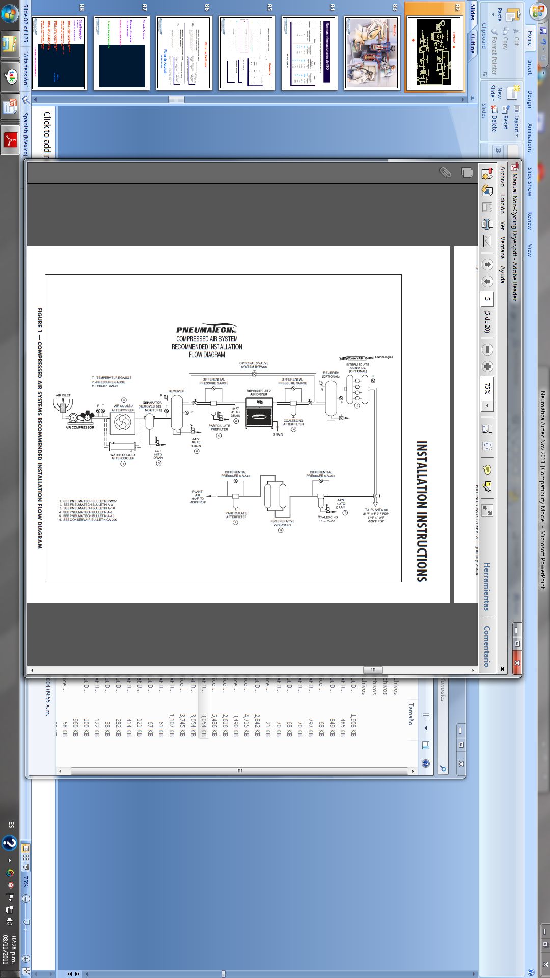
Two-tank system (recommended):

   Compressor → Aftercooler → WET TANK → Dryer → DRY TANK → Distribution
                     │            │          │        │
                     ▼            ▼          ▼        ▼
                 Separator    Primary    Treatment  Stable, dry
                              moisture    complete   air storage
                              removal
Wet Receiver (Primary Receiver)
Location: Immediately after aftercooler, before dryer
Functions:
- Radiant cooling surface (additional heat dissipation)
- Condensate collection point
- Dampens pulsations from compressor
- Provides buffer before treatment equipment
| Parameter | Typical Value |
|---|---|
| Location | After aftercooler, before dryer |
| Size | 1 gallon per CFM (minimum) |
| Pressure | Full compressor pressure |
| Condensate | Heavy - requires auto drain |
Dry Receiver (Secondary Receiver)
Location: After dryer, before distribution
Functions:
- Stores treated air for demand peaks
- Stabilizes system pressure
- Provides capacitance for control
- Reduces compressor cycling
| Parameter | Typical Value |
|---|---|
| Location | After dryer, before distribution |
| Size | 3-10 gallons per CFM |
| Pressure | Below tank pressure (regulated) |
| Condensate | Minimal - should be dry |
Single vs Dual Tank Systems
| Configuration | Pros | Cons |
|---|---|---|
| Single tank (wet) | Lower cost, simpler | Dryer works harder, less storage |
| Dual tank | Better moisture control, more storage | Higher cost, more space |
| Distributed storage | Point-of-use capacity | Requires multiple drains |
Use a wet receiver before the dryer and a dry receiver after. This protects the dryer and maximizes usable storage.
Tank Sizing Formulas
CAGI Sizing Rule
For load/unload compressors:
Where:
- V = Tank volume (gallons)
- C = Compressor capacity (CFM)
- Pₐ = Atmospheric pressure (14.7 psia)
- P₁ = Cut-out pressure (psig)
- P₂ = Cut-in pressure (psig)
- N = Allowable cycles per hour (typically 4-10)
Example:
- 100 HP compressor producing 450 CFM
- Cut-in: 100 psig, Cut-out: 110 psig
- Target: 6 cycles per hour
VSD Compressor Sizing
VSD compressors need less storage since they modulate:
Demand Event Sizing
For systems with large intermittent demands:
Where:
- Q_demand = Peak demand flow (CFM)
- Q_supply = Compressor output (CFM)
- t = Duration of demand event (minutes)
Example: 30-second blow-off using 200 CFM
- Compressor provides 100 CFM
- Allowable pressure drop: 10 PSI
System Capacitance
Total system storage includes all piping:
Where:
(D in inches, L in inches, result in gallons)
ASME Pressure Vessel Code
ASME Section VIII
ASME Boiler and Pressure Vessel Code, Section VIII governs compressed air receiver design and construction.
ASME Code Requirements:

┌─────────────────────────────────────────────────────────┐
│  ASME SECTION VIII - PRESSURE VESSELS                  │
├─────────────────────────────────────────────────────────┤
│  Division 1: General requirements (most common)        │
│  Division 2: Alternative rules (high-stress design)    │
│  Division 3: Alternative rules for high pressure       │
└─────────────────────────────────────────────────────────┘
Key ASME Requirements
| Element | Requirement |
|---|---|
| Material | ASME-approved materials (SA-516, SA-283, etc.) |
| Design pressure | MAWP clearly stamped |
| Welding | Certified welders, documented procedures |
| Inspection | Third-party inspection (Authorized Inspector) |
| Testing | Hydrostatic test to 1.3× MAWP |
| Documentation | Manufacturer's Data Report (U-1 form) |
| Nameplate | ASME U-stamp with all required data |
ASME Nameplate Data
ASME U-Stamp Nameplate:

┌────────────────────────────────────────┐
│              [ASME U STAMP]            │
│                                        │
│  MAWP: ______ PSI at ______ °F         │
│  MDMT: ______ °F at ______ PSI         │
│  Serial No: ______________             │
│  Year Built: ______                    │
│  Manufacturer: ________________        │
│  National Board No: ___________        │
└────────────────────────────────────────┘

MAWP = Maximum Allowable Working Pressure
MDMT = Minimum Design Metal Temperature
Non-ASME Vessels
Exempt from ASME code:
- Vessels ≤ 5 cubic feet AND ≤ 250 psig
- Vessels ≤ 1.5 cubic feet with no pressure limit
Using non-ASME vessels above exemption limits:
- Violates OSHA regulations
- Voids insurance coverage
- Creates liability exposure
- May incur regulatory fines
Pressure Relief Requirements
ASME Relief Valve Sizing
Where:
- A = Required orifice area (in²)
- Q = Required relieving capacity (CFM)
- C = Coefficient (356 for air)
- K = Valve coefficient (typically 0.975)
- P₁ = Set pressure + overpressure (psia)
- M = Molecular weight (29 for air)
- T = Temperature (°R)
Relief Valve Requirements
| Parameter | Requirement |
|---|---|
| Set pressure | ≤ MAWP of vessel |
| Capacity | ≥ Compressor output at MAWP |
| Type | ASME-certified, UV-stamped |
| Testing | Annual inspection recommended |
| Discharge | Piped to safe location |
Relief Valve Installation
Correct installation:

         ┌─── Relief valve (no shutoff between valve and vessel)
         │
         ▼
    ┌─────────┐
    │ ░░░░░░░ │
    │ ░VESSEL░│
    │ ░░░░░░░ │
    └─────────┘

NEVER install:
- Shutoff valve between relief and vessel
- Reducer below relief valve size
- Relief valve in discharge piping only
All pressure vessels require:
- Relief valve rated for maximum working pressure
- Pressure gauge for monitoring
- Regular inspection and testing
Relief valves protect against over-pressurization. Never block or disable them.
Inspection Requirements
Frequency Guidelines
| Jurisdiction | Typical Requirement |
|---|---|
| OSHA (general) | Initial + as needed |
| State/local | Often annual internal + external |
| Insurance | Per insurer requirements |
| National Board | Follow NB-23 guidelines |
Inspection Points
| Component | What to Check |
|---|---|
| Shell | Corrosion, pitting, bulging |
| Welds | Cracks, corrosion at heat-affected zones |
| Nozzles | Corrosion, thread damage |
| Relief valve | Operation, corrosion, proper set pressure |
| Drain | Function, corrosion |
| Supports | Corrosion, structural integrity |
| Nameplate | Legible, attached |
Thickness Testing
Ultrasonic thickness (UT) testing determines remaining wall:
Where:
- t_actual = Current measured thickness
- t_minimum = Minimum required by code
Silencing
Compressed air exhausting to atmosphere creates significant noise. Solutions:
- Exhaust silencers/mufflers
- Diffusers
- Gradual pressure release
Condensate Management
Drain Types
| Drain Type | Operation | Pros | Cons |
|---|---|---|---|
| Manual | Operator opens valve | Simple, cheap | Requires attention, often forgotten |
| Timer | Opens on schedule | Automatic | Wastes air if timer misadjusted |
| No-loss (float) | Opens when liquid present | No air loss | Mechanical parts can fail |
| Electronic level | Sensor triggers drain | No air loss, reliable | Higher cost |
Timer Drain Waste
Timer drain air loss calculation:

If drain opens 10 sec every 5 min at 100 psig:
- Air loss per cycle ≈ 0.5 CFM × 10 sec = 0.08 CF
- Cycles per hour: 12
- Air loss per hour: 0.96 CF
- Annual air loss: 8,400 CF
- Annual cost @ $0.25/1000 CF: ~$2,100

Solution: Install no-loss drain
No-loss drains typically pay for themselves in 6-12 months through reduced air loss.