Filtration in Detail
Filtration is essential for removing contaminants from compressed air and protecting equipment and products.
The Contamination Problem
Contaminants in Compressed Air
- Water - Moisture condensed during compression
- Oil - From lubricated compressors
- Particles - Dust, rust, pipe scale
- Microorganisms - Bacteria, mold
The Compressor Multiplies Contaminants
Liquids and solids cannot be compressed - they multiply in concentration.
Compression Ratio Example:
Contaminants are now 10x more concentrated!
Filter Types
1. Particulate Filters
- Air flows from outside to inside the element
- Remove solid particles
- Efficiency: 3+ microns
- Pressure drop: ~0.25 PSI (dry)
- Material: Pleated cellulose
Applications: First line of defense, coarse particle removal
2. Coalescing Filters
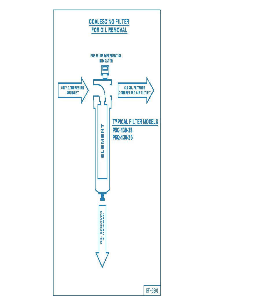 Coalescing filters capture oil aerosols and fine particles, draining collected liquids.
- Air flows from inside to outside the element
- Remove oil aerosols and fine particles
- Material: Microglass fiber
Coalescing Filtration Grades
| Grade | Efficiency | Oil Content | DP (dry) | DP (wet) |
|---|---|---|---|---|
| Grade 2 | 99.999% | 0.001 ppm | 1.5 PSI | 4-6 PSI |
| Grade 4 | 99.995% | 0.03 ppm | 1.25 PSI | 3-4 PSI |
| Grade 6 | 99.97% | 0.08 ppm | 1.0 PSI | 2-3 PSI |
| Grade 8 | 98.5% | 0.2 ppm | 0.5 PSI | 1-1.5 PSI |
| Grade 10 | 95% | 0.83 ppm | 0.5 PSI | 0.5-1 PSI |
3. Activated Carbon Filters
- Air flows from outside to inside
- Remove odors, tastes, and hydrocarbon vapors
- Efficiency: 99%
- Pressure drop: ~1 PSI
- Essential for breathing air and food applications
Condensate Separation
Centrifugal Separators
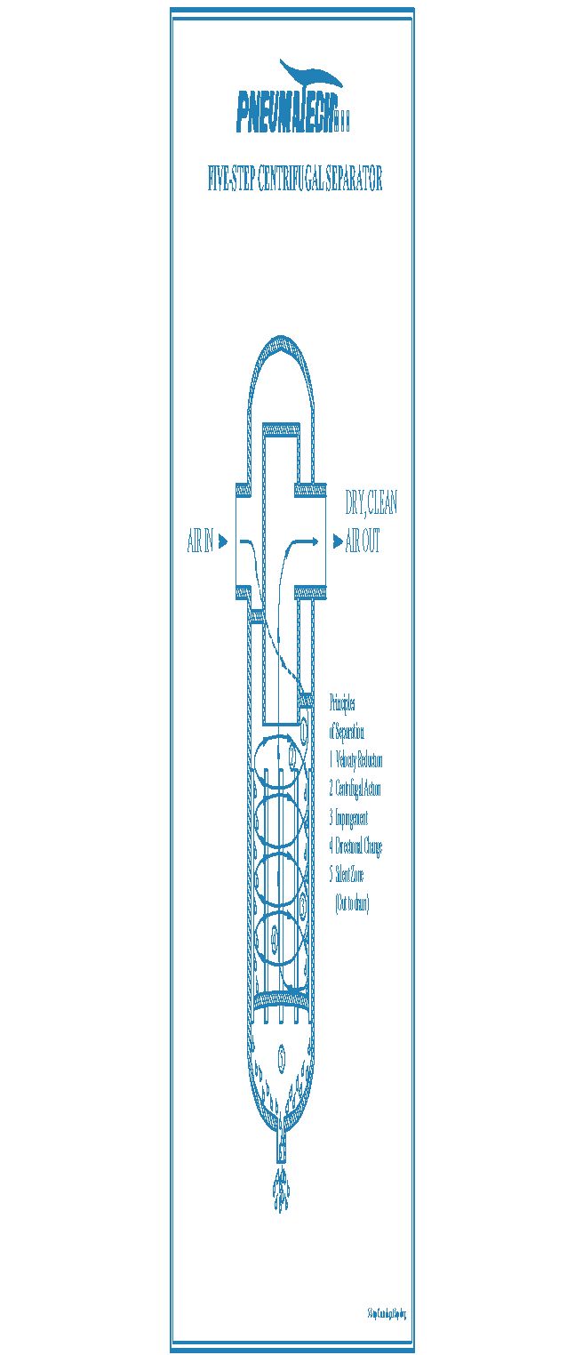 A 5-step centrifugal separator removes 99% of liquids and solids larger than 10 microns.
Separation Principles:
- Velocity reduction
- Centrifugal action
- Impact (collision)
- Direction change
- Quiet zone (settling)
Filter Selection Guide
| Application | Recommended Filtration |
|---|---|
| Pneumatic tools | Particulate + Coalescing (Grade 6-8) |
| Spray painting | Particulate + Coalescing (Grade 4) + Carbon |
| Food processing | Particulate + Coalescing (Grade 2) + Carbon |
| Electronics | Particulate + Coalescing (Grade 2) |
| Breathing air | Full treatment + Carbon + Monitoring |
The Cost of Pressure Drop
Every PSI of pressure drop costs money:
Example: 50 HP Compressor @ 250 CFM
| Component | ΔP | Annual Cost |
|---|---|---|
| Filter (5 PSI) | 5 PSI | $1,435 |
| Dryer (15 PSI) | 15 PSI | $4,312 |
Monitor differential pressure across filters. Replace elements before excessive pressure drop wastes energy.
Filter Media Types
Depth vs Surface Filtration
Depth Filtration:              Surface Filtration:
(Particles trapped throughout)  (Particles on surface)

    ░░░●░░░░░░░░                ●●●●●●●●●●●●
    ░░░░░░●░░░░░                ────────────
    ░░●░░░░░░░░░                │          │
    ░░░░░░░░●░░░                │          │
                                │          │

Best for: Oil aerosols          Best for: Dry particles
| Media Type | Material | Application | Efficiency |
|---|---|---|---|
| Microglass | Borosilicate fibers | Coalescing | 99.9999% @ 0.01μm |
| Cellulose | Wood pulp fibers | Particulate pre-filter | 95% @ 3μm |
| Polypropylene | Synthetic fibers | Chemical resistant | 99.9% @ 1μm |
| Stainless mesh | Woven metal | High temp, reusable | 90% @ 10μm |
| Activated carbon | Coconite/coal | Vapor adsorption | 99% (hydrocarbon) |
| PTFE membrane | Teflon | Sterile/pharma | 99.99% @ 0.01μm |
Coalescing Media Structure
Three-layer construction:

Outer layer: Drainage
├── Coarse fibers
├── Allows liquid drainage
└── Protects inner layers

Middle layer: Coalescing
├── Fine microglass (2-5 μm)
├── Captures and combines droplets
└── Primary filtration zone

Inner layer: Pre-filtration
├── Medium fibers
├── Captures large particles
└── Protects coalescing layer
Beta Ratio (Filtration Efficiency)
The Beta ratio (β) quantifies filter efficiency for a given particle size.
Definition
Efficiency Conversion
\text{Efficiency (%)} = \frac{β - 1}{β} \times 100 = \left(1 - \frac{1}{β}\right) \times 100| Beta Ratio | Efficiency | Meaning |
|---|---|---|
| β₂ = 2 | 50% | Half of 2μm particles pass |
| β₂ = 10 | 90% | 1 in 10 pass |
| β₂ = 100 | 99% | 1 in 100 pass |
| β₂ = 1000 | 99.9% | 1 in 1,000 pass |
| β₂ = 10,000 | 99.99% | 1 in 10,000 pass |
A "β = 1000" rating is meaningless without particle size. Always specify: β₃ = 1000 means 99.9% efficient at 3 microns.
Test Standards
| Standard | Method | Notes |
|---|---|---|
| ISO 12500-1 | Oil aerosol efficiency | Industry standard |
| ISO 12500-3 | Particulate efficiency | Multi-pass test |
| DIN 24550 | Older European standard | Being phased out |
Filter Placement Strategy
System Layout
Optimal filter placement:

                   Point-of-Use
                   Filter
                      │
    Compressor → Wet Tank → Dryer → Dry Tank → Distribution → Application
         │           │        │        │              │
         │      Separator  Pre-filter  After-filter   Final filter
         │           │        │        │              │
         ▼           ▼        ▼        ▼              ▼
    Aftercooler   Bulk      Protect   Polish      Process
    + separator   liquid    dryer     air         specific
                  removal   media     quality     needs
Pre-Dryer Filtration
Purpose: Protect dryer from oil and particles
| Dryer Type | Pre-Filter Requirement |
|---|---|
| Refrigerated | Particulate filter (5μm) |
| Desiccant | Coalescing (Grade 6) + particulate |
| Membrane | Coalescing (Grade 4) + particulate |
Oil contaminates desiccant permanently. Always install coalescing filter upstream of desiccant dryers.
After-Dryer Filtration
Purpose: Remove any desiccant dust or particles from dryer
| Application | After-Filter |
|---|---|
| General plant | Particulate (3μm) |
| Instruments | Coalescing (Grade 4) |
| Sensitive process | Coalescing (Grade 2) |
Point-of-Use Filtration
Purpose: Final protection for specific applications
| Application | Point-of-Use Filter |
|---|---|
| Pneumatic tools | 40μm + lubricator |
| Paint spray | 5μm + activated carbon |
| Food contact | 0.01μm sterile + carbon |
| Electronics | 0.01μm + carbon |
| Breathing air | Full treatment + CO monitor |
Filter Sizing
Flow Capacity
Size filters for actual flow conditions:
Sizing Rules
| Guideline | Reason |
|---|---|
| Size for peak flow, not average | Prevents excessive ΔP at surge |
| Use 70% of rated capacity | Allows for filter loading |
| Consider future expansion | Filters are cheap, ΔP is expensive |
Example:
- Application needs 500 CFM peak
- Select filter rated for 500 ÷ 0.7 = 715 CFM minimum
Filter Maintenance
When to Change Elements
| Indicator | Action |
|---|---|
| ΔP > 10 PSI (coalescing) | Replace |
| ΔP > 5 PSI (particulate) | Replace |
| 12 months of operation | Evaluate condition |
| Color change | Inspect element |
| Oil carryover | Check drain and element |
Differential Pressure Monitoring
ΔP gauge installation:

    Upstream    Filter     Downstream
    pressure   housing    pressure
        │         │           │
        ▼         ▼           ▼
    ┌───●────┬────────┬───●───┐
    │        │░░░░░░░░│       │
    │        │░░░░░░░░│       │
    │        │░░░░░░░░│       │
    └────────┴────────┴───────┘
             │
        ┌────┴────┐
        │   ΔP    │
        │  Gauge  │
        └─────────┘
| Element State | Typical ΔP |
|---|---|
| New (dry) | 0.5-1 PSI |
| New (wet/operating) | 1-3 PSI |
| Replace soon | 6-8 PSI |
| Replace now | >10 PSI |
Common Mistakes
- Ignoring pressure drop - Wastes energy
- Forgetting to drain condensate - Re-contaminates the air
- Wrong sequence - Filters before dryer
- Undersizing - Causes excessive pressure drop
- Using wrong element - Voids warranty, poor performance
- Cleaning and reusing - Damages media structure