Master Controllers
A master controller (sequencer) coordinates multiple compressors to optimize overall system efficiency. It's the "brain" that makes decisions about which compressors to operate and how.
Main Functions
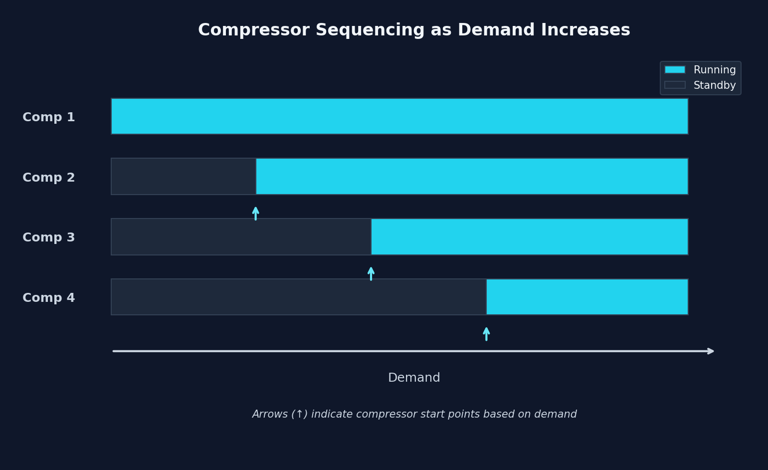
Sequencing
Determines the start and stop order of compressors:
Load Balancing
Distributes load among available compressors:
Without balancing:           With balancing:

Comp 1: 100% ████████████   Comp 1: 75% ██████████
Comp 2: 100% ████████████   Comp 2: 75% ██████████
Comp 3:  50% ██████         Comp 3: 75% ██████████
Comp 4:   0% ░░░░░░░░░░░░   Comp 4: 75% ██████████

Uneven wear                  Uniform wear
Lead Rotation
Periodically changes the lead compressor:
| Week | Lead | Second | Third | Standby |
|---|---|---|---|---|
| 1 | Comp 1 | Comp 2 | Comp 3 | Comp 4 |
| 2 | Comp 2 | Comp 3 | Comp 4 | Comp 1 |
| 3 | Comp 3 | Comp 4 | Comp 1 | Comp 2 |
| 4 | Comp 4 | Comp 1 | Comp 2 | Comp 3 |
Hour Equalization
The controller starts the compressor with fewest hours first:
Accumulated hours:

Comp 1: 12,500 h ████████████████████████████████████
Comp 2: 11,800 h ██████████████████████████████████
Comp 3: 10,200 h █████████████████████████████
Comp 4:  9,500 h ███████████████████████████
                 ↑
                 Starts first
Control Logic
Pressure Band Control
Pressure (bar)
    │
 8.0├────────────────── Upper limit (all OFF except minimum)
    │
 7.8├────────────────── Unload point Comp N
    │
 7.6├────────────────── Unload point Comp 2
    │
 7.4├────────────────── Unload point Comp 1 (trim)
    │   ════════════════ OPERATING BAND ══════════════
 7.2├────────────────── Load point Comp 1 (trim)
    │
 7.0├────────────────── Load point Comp 2
    │
 6.8├────────────────── Load point Comp N
    │
 6.5├────────────────── Lower limit (emergency)
    │
Flow-Based Control
Some systems use flow measurement:
┌─────────────────────────────────────────────────────────┐
│                    CONTROLLER                            │
│                                                          │
│   Measured flow: 2,500 CFM                              │
│   Current capacity: 3,000 CFM (Comp 1 + Comp 2 + Comp 3)│
│                                                          │
│   Decision: Reduce capacity                             │
│   Action: Unload Comp 3                                 │
│                                                          │
└─────────────────────────────────────────────────────────┘
Typical Configuration
Setpoint Parameters
| Parameter | Typical Value | Description |
|---|---|---|
| Target pressure | 7.0 bar | Main setpoint |
| Dead band | 0.2 bar | No action |
| Load differential | 0.3 bar | To start next |
| Unload differential | 0.3 bar | To stop compressor |
| Start delay | 30-60 sec | Avoid cycling |
| Stop delay | 60-180 sec | Avoid cycling |
Configuration Example
Setpoints for 4-compressor system:

                    Comp 1    Comp 2    Comp 3    Comp 4
                    (Trim)    (Base)    (Base)    (Standby)
Load                7.0 bar   6.8 bar   6.6 bar   6.4 bar
Unload              7.4 bar   7.6 bar   7.8 bar   8.0 bar
Load delay          0 sec     30 sec    60 sec    90 sec
Unload delay        60 sec    90 sec    120 sec   150 sec
Operating Modes
Automatic Mode
┌─────────────────────────────────────────────────────────┐
│                    AUTOMATIC MODE                        │
│                                                          │
│  ┌────────┐    ┌────────┐    ┌────────┐    ┌────────┐  │
│  │ Comp 1 │    │ Comp 2 │    │ Comp 3 │    │ Comp 4 │  │
│  │  AUTO  │    │  AUTO  │    │  AUTO  │    │ STANDBY│  │
│  │ ████   │    │ ████   │    │ ░░░░   │    │ ░░░░   │  │
│  │  ON    │    │  ON    │    │  OFF   │    │  OFF   │  │
│  └────────┘    └────────┘    └────────┘    └────────┘  │
│                                                          │
│  Decisions made by controller                           │
└─────────────────────────────────────────────────────────┘
Manual Mode
┌─────────────────────────────────────────────────────────┐
│                     MANUAL MODE                          │
│                                                          │
│  ┌────────┐    ┌────────┐    ┌────────┐    ┌────────┐  │
│  │ Comp 1 │    │ Comp 2 │    │ Comp 3 │    │ Comp 4 │  │
│  │ MANUAL │    │ MANUAL │    │ MANUAL │    │ MANUAL │  │
│  │ [ON]   │    │ [OFF]  │    │ [ON]   │    │ [OFF]  │  │
│  └────────┘    └────────┘    └────────┘    └────────┘  │
│                                                          │
│  Warning: Operator controls each compressor individually │
└─────────────────────────────────────────────────────────┘
Emergency Mode
Activated when pressure drops below limit:
CRITICAL PRESSURE DETECTED: 6.2 bar

AUTOMATIC ACTION:
├── Start ALL available compressors
├── Ignore start delays
├── Activate audible alarm
├── Send notification
└── Log event
Manufacturers and Models
| Manufacturer | Model | Features |
|---|---|---|
| Atlas Copco | Optimizer 4.0 | Integrated IoT, cloud |
| Ingersoll Rand | X-Series Controller | Modular, touchscreen |
| Kaeser | Sigma Air Manager | High precision, efficient |
| SMC | Air Management System | Compact, economical |
| Compressor Controls | AutoComp | Heavy industrial |
| Case Controls | AirMaster+ | Industry standard |
PLC Integration
Typical Signals
From master controller to PLC:
| Signal | Type | Description |
|---|---|---|
| System pressure | Analog 4-20mA | Current value |
| Compressor status | Digital | ON/OFF each |
| Active alarm | Digital | System fault |
| Total flow | Analog 4-20mA | Total CFM |
From PLC to master controller:
| Signal | Type | Description |
|---|---|---|
| Enable system | Digital | General permissive |
| Remote setpoint | Analog 4-20mA | Target pressure |
| Compressor lockout | Digital | Inhibit specific |
| Alarm reset | Digital | Reset pulse |
Connection Diagram
┌─────────────────┐         ┌─────────────────┐
│   PLANT PLC     │         │    MASTER       │
│                 │         │   CONTROLLER    │
│                 │         │                 │
│  AI ←──────────────────── AO Pressure      │
│  AI ←──────────────────── AO Flow          │
│  DI ←──────────────────── DO Status        │
│  DI ←──────────────────── DO Alarms        │
│                 │         │                 │
│  AO ───────────────────→ AI Setpoint       │
│  DO ───────────────────→ DI Enable         │
│  DO ───────────────────→ DI Reset          │
│                 │         │                 │
└─────────────────┘         └─────────────────┘
Quantifiable Benefits
| Benefit | Typical Savings |
|---|---|
| Pressure band reduction | 1-3% per 2 PSI |
| Elimination of compressor "fighting" | 5-10% |
| Start optimization | 3-5% |
| Hour equalization | 20-30% service life |
| Early fault detection | 50% downtime reduction |
Investment Justification
A master controller typically costs 0.10/kWh, a 10% savings represents $30,000/year. ROI under 2 years.